| THE HIGH RELIZATIONS |
This
is the first project in the Electronic Field ( Hi my schematic teacher Mr Mack who gave me
some help when I need it and to others unforgetable teachers Mr Steinmetz et Mr J-P
Muller).
I wanted to realize something great I to close succesffully two years of labour.( I was
not good in Electronic when I got my degree two years before). What a funny Idea I got
then when I studied
in 1995 at the Louis Armand of Mulhouse (France). As far as I can remember, I was trying
to make this works and debug it two days before passing my exams- that was very crazy!!!.
Like every poor student, I did have neither a scope (to see electric signals) nor a Signal
Generator at home - so I decided to build one. My principal hobby was the Hp48 and we
organize many meetings
during the school with friends. I wondered. if it was possible not use the screen of
the hp to display Electric signal curves. I conclued by the fact this will be possible by
using the serial link of the HP
to get the datas to plot. This was mainly an Interface problem - I call the advanced
interface ab48 (for Hp48 Laboratory) where you can see below the schematics: 
Ooh dear, there's a lot of stuff required... To build a such
card, you should buy an old UART chip (Universal Asynchronous Receiver
Transmitter).As
I have already mentionned , this chip is parametrized by connecting in hardware Levels on
the pins. In our case, the transmission rate is limited by the hp
at 9600 bauds without parity bit and one stop bit.
For those who read the chapter Simplified THEORY, it will be no difficult:
-to find the two adapters RS232<->TTL (line drivers DS14C89 on the top left
corner plus the Q1 transitor on the top right corner).
-to notice a 16 times frequency clock (baud generator part) required by the UART to :
decode any serial frame on the port
RX_LIB to parallel data bits on RD1 à RD8.
encode inside an rS232 frame the 8 binary
data bits 8 given on DB1 to DB8 with a timing set with an multivibrator NE555 (U7)
To measure an analog Signal on VE-IN (max +5V , min -5V) , we use an cheap 8-bit
Analog Digital Converter the ADC804 and send the converted data to the HP.
thus a low frequency scope is made. To produce an analogic signal, I have bought an
DAC808 , an 8-bit Digital to Analog Converter which delivers an current so
an curent to voltage U10B structure is needed. For security reasons, I have added an
adaptor level U10A to allow to sink 20mA without a drop voltage of VS .
Unfortunately, the Operational Amplifier (AOP 10A et 10B) has a
bad effect : an internal voltage drop of 1 volt. In fact, if you power an AOP with +5V/-5V
you will only get +4/-4V a outputs (loss of 1 volt due to the two junctions of
transistors). This is not suitable as we want to build a signal generator
+5V/-5V and not +4V/-4V.
To solve this problem, I power the AOP on a SCHENKEL type doubbler, which generates
+7.5/-7.5V with a power of +5/-5V.
Many of you will notice the extra jumper Cav1 (on the top left corner). It it a chooser
between either the 8 digital input or the Analog Input (but not the both at same
time).
there are two precision potentiometers P11 et P12 to set the optimal duration between two
successive frames.(see the interface adaptator to learn how to do it).
For the values , use P12=1k and P11=50k .
I have made the programs in RPL language (oh yes again), all the
construction files will be available here soon. I will make some screenshots Just to see
It is not a joke.
 |
In the center, you can see the Lab48 board where you
can miss the 'UART AY31015-D chip
(this is the biggest chip at the bottom of the board)
Next to it, my HP48 linked by the serial wire in scope mode. It displays an
periodical signal coming from the NE555tiny board at the left of the yellow mutlimeter.
I used both the analog output to generate 3.48V and the digital outputs linked to my test
poard on the top left corner. Unfortunately we can't see the 8 red leds.
On the right top corner, here is my symetric power supply +5/-5V with two extra coolers
(it does never serve :-)) to power . Lab48 with 3 wires (red blue and black) and
also my test board. |
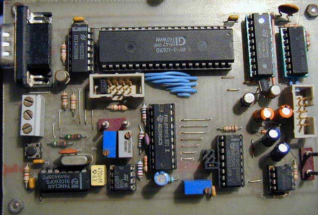
Let's have a closer look of the board:
However, take in mind that with a such board, It can not replace a classic scope as over
30Hertz signal
you can't see well the curves (the resolution of hp is so poor) but it is a beginning.
|
