| THE HIGH RELIZATIONS |
I - THE BASIS OF COMMUNICATIONS
To engage a communication between two systems
(machines,humans,..), you should bring together 3 conditions:
1) same physical support
Available:: coaxial wire, optical fiber,
infrared module,antenna,.... There is no doubt that you will
not manage to command your tv vith optical fiber (there is no
plug for it) butr with an infrared remote control as the tv
includes an infrared receiver.. The interfaces to establish
dialog (emitter,receiver) must be compatible to work.( same
technical features).
2) same transmission type
- synchronous :The datas exchanged
are synchronyzed by a clock sent on an additional canal . The
receiver is the slave of the emitter and is in addition triggered
by the clock. The clock period can vary even during the transmission,
it doesn't matter as the receiver follows it.
- asynchronous: The datas are delimited
by one or more synchronisazion tops. The first , called start
stop , allows the receiver to get ready for the datas sent behind.
The speed of transmission who fixed et must be the same on the
reveiver and emitter , can't change during a transfert. Here,
again, the receiver depend on the emitter as it must got the
same speed clock to decode successfully datas.If the emitter
speed is changed , the receiver must be reparametrized to match
the changes..
3) same protocol
There is an agreement between the two
system concerning the content to be transmitted (format of the
frames). If the receiver expects to get un serial frame with
a specific format, I should send to it a serial frame with the
same specific format so that it will be able to understand me..
Thus, the protocol defines the rules of interpretation for a
frame.
What you should undertand is that at
this level , I don't mind what sort of system I want to establish
the dialog. (I don't want to hear things like: does it work
with an HP3x or HP4x or PC ..). All I need to know is if whether
yes or not a machine got the possibility to dial. ie does this
machine include an serial , infrared interface or communication
port?
Two possibilities , yes or no. In this last case, you will have
to built an adapation interface ; that is waht I have done with
the multiusage infrared as my microcontroler is not sold with
an infrared interface. If this problem is solved , it means
that if I satisfy the two previous conditions (same transmission
type and protocol) ....then I succeed in establishing a
communication canal.
Whatever the usage you will do of this canal (video, sound,data)
It is the same for me àll conditions are satisfied and
the speed does not cause troubles for the protocol.
II - THE LIMITS OF THIS STUDY
I won't describe synchronous links but
prefer get involved in asynchronous links who are around us every
days.Through pratical examples such as RS232 serial link , infrared
link of the H48s(x)/g(x)) and remote control (TV,tape recorder,hifi)
protocols, I will try to expose the méthodology to establish
the links between two systems incompatibles. This leads me to
build a model for the data transferts (including all possibilites)
and to choose adaption interfaces.This last part is however difficult
for an electronic newbie but don't worry , I will explain physicaly
what happens with scope pictures.
1) Universal model for the asynchronous
frame
A) Frame
A frame trame is the succession of elements
inside a start header , group header and a stop header.
|
Start
header of elements
|
Group
header 1,...,n of elements
|
Stop
header of elements
|
|
|
|
|
|
|
|
|
|
| START_TRAME |
CONTROL_TRAME |
|
(n times)
|
|
| |
|
|
|
|
|
| START_ELEMn |
CONTROL_ELEMn |
DATA_ELEMn |
CONTROL_ELEMn |
STOP_DATAn |
|
B) Blocks
As shown , every element (Start,1,2,..n,stop)
can be splitted into several blocs.
These blocks can be grouped by types:
|
TYPE
|
DESCRIPTION
|
| START |
warns the receiver and
prepare the analysis of the
element , it is generally the first bloc of the element. |
| DATA |
contains the datas to
transfert (voice,sound ,video..) |
| CONTROL: |
Ensure the integrity
of the datas, and the organizations of datas blocks or specify
the destinator |
| STOP |
Mark the end of an Element
, .optionnal if control block defines the size of this block |
C) Patterns
Unfortunately , a bloc can't be transmitted as it is.It must
be blown up in binary elements (value 0 or 1) I call: Pattern.
For example if the DATA block DATA_ELEMn is a char, it will
be represented by m=8 patterns: D0 to D7.
|
DATA_ELEMn
|
|
|
|
| D0 |
D1 |
D2 |
D3 |
D4 |
D5 |
D6 |
D7 |
|
ou |
|
DATA_ELEMn
|
|
|
|
| D7 |
D6 |
D5 |
D4 |
D3 |
D2 |
D1 |
D0 |
|
There is two way to organize o block
: you can start by 0 motif (the LSB, Least Significant Bit )
and by the m-1 pattern (the MSB, Most significant Bit) or the
inverse. So take care of this! In both cases , the (decimal)
value of a DATA_ELEM block is:
DATA_ELEMn=D0*2^0 + D1*2^1 + D2*2^2
+ D3*2^3+D4*2^4+D5*2^5+D6*2^6+D7*2^7;
This can be generalized
by the relation:
|
 |
with
m the number of pattern of the block and Valeurmotif(k), the
binary value of the k pattern.
a) Definition of a pattern:
Physically, the patterns are translated
into an electrical waveform which can take two tension levels
depending on the pattern value. The duration of the signal
is called total pattern duration. The waveform and the combination
of the blocks patterns make a frame according to protocol
you use. There only two data patterns for a specific protocol
as a pattern can represent either 0 or 1..
To define a pattern :
#You have to name it in relation
with the order, it occupies in the block.
#Precise electrical features such as:
- its start value (0 or 1),
- the (total) pattern duration,
- its duty cycle (between 0 and
1): division between the high level duration by the total
duration
- its end value (0 or 1)
| To understand this
I have made for you... |
|
A START pattern can be different from a DATA ,CONTROL, STOP
pattern however keep in mind that the START pattern START
is constant and a frame without DATA pattern has no sense.
b) Pattern granularity
Group of patterns inside a same block
inherit from the type of the block. Each block can be organized
as you wish, this is the pattern distribution principle into
a block. Thus, if you want send two differents type of data
in a frame, this is possible only if you define a limit between
these inside the DATA block type.. The data patterns will
represent as well an integer as a list ... wich will be greater
in size that the data patterns in a single frame. No problem,
we will transfer those data objets with multiple frames, this
is the encoding process of the datas. You should consider
to rebuild the full data objects at the end thanks to the
decoding process. These two tasks are done done with a specific
communication software relative to the choosen protocol.
c) Durations
I call the inter-frame duration, the
duration between the last pattern of a frame and the first
pattern of the following frame. The duration of a pattern
is generaly the same between blocks.In the case of the RS232
link or HP48 IR link, it corresponds to the speed of transmission
(1/(Value in Bauds)). If I set up the serial port PC at 9600
bauds, the duration of the pattern will be 1/9600=104 microsecondes.
2) Sumary
Maybe you noticed that I use the communication basis by giving
my rules and notations (rule 3: talk the same language!). The
important thing, I hope you understood, is that a frame is a successive
group of blocks including patterns. These patterns can be electricaly
represented : a piece of an electric signal containing the value
of the pattern. The frame is thus the result of all "electrical"
patterns stuck together, taking account the order in the block
and the order of the block in the frame..
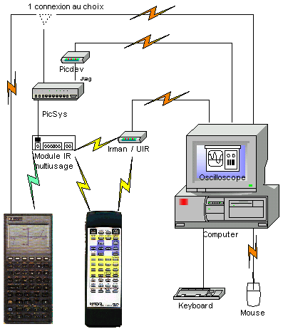
3) Testing architecture
On the picture below , I show the communication
links I have studied..
CClick on the picture and discover the
element's feature.
|