| THE HIGH RELIZATIONS |
We
have seen in the previous chapter my pic programmer, let's have a look on the target
circuit : picsys .
The usage of this card will be a domotic center to link th HP to the
PC by infrared, to decode remote frames to control the PC(like the
Irman module/UIR) and
make the inverse (The PC will be able to trigger any domestic stuff by IR). Many friends
asked me if it was possible to get/send on PC the picts and rings of their
handphone or their favorite PDA (PSion, Palm , Razor...). Yes , I answered , wtih this
modular card, all is possible from mouse simulation, keyboard wireless, to madness
things such as a tiny webserver!!!!
I- Schematic:
II - Outlines
In fact, I have build a embedded box with a 16F84 pic , a max232 and
connectors.
The Frontend with leds is used to see what happens . In general , in all
embedded system, you sould add a display and write drivers for it.
To make the tests, I have bound the 10 wire I/0 (network) available on the
leds panel with a HE14.(2*7pin) type connector.
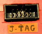
The J-TAG interface is on the right side whereas the serial
port (COM1) the Input/Outputs port (NETWORK) are both on the left side.
We can notice on the open assembly that the leds panel is linked to the card by two wires
: a black (the ground) and a white (+5V) . Thus, the red led (the most in the right on the
photo) is ON as I powered the circuit in standalone mode .(ie the programmer
is not connected)
The optimisation is complete, there is no place left.
III- Layout
A- Main board
The C condensator( (in the middle) is a
decoupling condensator of 100nF.
I
forgot to tell you something very important:
- This
circuit was originaly designed to communicate with the PC thanks
to a 3 wire not crossed.DB9 female/DB9 female (pin 2 of thePC=pin
2 of port P1 ; pin 3 PC=pin 3 of port P1;pin 5 of the PC=broche
5 of port P1) . Furthemore, I use the
terminator freeware
to send or receive characters from the PC.
- If
you wish link your HP 4x or HP3x to it throughout the HP wire,
you should exchange the 2 wire with 3 wire on the P1connector:
-by building an additionnal cross wire DB9 male / DB9 female.
-by correcting it on the board (if you do so , please remember
to use a cross cable to link the board to the PC ).
B- Leds panel
I put transparent leds (green when ON) in zigzag on 3 tylip
raws . I used two network resistors 1k* 8+1CP, where the commun
point is at the ground. I will
not describe how to connect in serial 8 leds to
a nework resistor but I prefer to show my K2000 caterpilar
as it is a efficient way to tests leds one after the other and I/O
port definition.
 The caterpilar (in the middle) let steps behind it. The caterpilar (in the middle) let steps behind it.
Here is the optimized release of the program as I synchronize
it on timer0: It takes 255*256*8 microseconds ~0.5 seconds to caterpilar
to reach one end
| K2000.c
program |
Include
file : include/mapping.h |
#include <pic.h>
#include <mapping.h>
__CONFIG(FOSC0|PWRTE|CP);
/*************************************
B release: K2000 Timer0 added
**************************************/
#define PORTBIT(adr, bit) ((unsigned)(&adr)*8+(bit))
#define POLLING_PERIOD 255
//TMRO=255 microseconds
#define TMR0_SETTING (0xFF-(POLLING_PERIOD-5)) //adjustment
#define TMR0_PRESCALER 0b111 //256 prescaler of TMR0
#define ITMask 0B10000000
volatile union PORTIO PORT @ 0x05;
volatile union DATABYTE Buff;
volatile unsigned char Up;
volatile unsigned char Timer;
void WriteParport(void);
void ReadParport(void);
main()
{
unsigned k;
// unsigned t;
TRISB = ITMask;
TRISA = 0;
PORTA = 0;
PORTB = 0;
Up=1;
Timer=0;
k=0;
//Timer
OPTION&=0B11000000; //turn 0ff bottom 6bits to configure
tmr0
OPTION|=TMR0_PRESCALER;
T0IE=1;
GIE=1;
//Start Kit :-)
for(;;) {
if(Timer) { //when the time TMR0 is due..
WriteParport();
//We flush 8 bits on the leds
//K2000 test
if(Up) { //Aller
k=k+1;
if(k==7) {
Up=0;
}
} else { //Retour
k=k-1;
if(k==0){
Up=1;
}
}
Buff.BYTE=1<<k;
Timer=0;
}
}
}
void WriteParport(void) {
PORT.BYTE.MSB=Buff.FIELD.MSB;
PORT.BYTE.LSB=Buff.FIELD.LSB;
}
void ReadParport(void) {
Buff.FIELD.MSB=PORT.BYTE.MSB;
Buff.FIELD.LSB=PORT.BYTE.LSB;
}
interrupt isr()
{
if(T0IF) {
TMR0=TMR0_SETTING;
T0IF=0;
Timer=1;
}
}
|
#ifndef MAPPING_H
#define MAPPING_H
typedef union DATABYTE {
unsigned char BYTE;
struct{
unsigned char LSB:4;
unsigned char MSB:4;
} FIELD;
struct{
unsigned char D1:1;
unsigned char D2:1;
unsigned char D3:1;
unsigned char D4:1;
unsigned char D5:1;
unsigned char D6:1;
unsigned char D7:1;
unsigned char D8:1;
} BIT;
} _DATABYTE;
typedef union PORTIO {
unsigned int WORD;
struct {
unsigned char D1:1; //Alias for RA0
unsigned char D2:1; //RA1
unsigned char D3:1; //RA2
unsigned char D4:1; //RA3
unsigned char RS_OUT:1; //RA4
unsigned char NC:3; //NC
unsigned char D5:1; //RB0
unsigned char D6:1; //RB1
unsigned char D7:1; //RB2
unsigned char D8:1; //RB3
unsigned char TC_IN:1; //RB4
unsigned char HP_IN:1; //RB5 or D9
unsigned char HP_OUT:1; //RB6 or D10
unsigned char RS_IN :1; //RB7
} BIT;
struct {
unsigned char LSB:4;
unsigned char NC2:4;
unsigned char MSB:4;
} FIELD;
struct {
unsigned char LSB;
unsigned char MSB;
} BYTE;
};
#endif
|
|
|
WARNING!!, I have found a bug in the the
piclite C compiler 7.85. The transfer of bitfields greater than
7 between two union structures is faulty. There the bitfields are
bad positionned intot the end structure!! In this sample, I have
been lucky as I transfert only 4 bit width bitfields so it works
fine. I send an Email to the technical support, they simply told
me that it was certainly fixed in the commercial release. Really?
What a joke!
|