THE
SIMPLIFIED THEORY |
In general,
the electric signals from a I/O port are not directly usable. An interface is required and
we call it line drivers.What is important to understand is that the interface and
encoders/décoders (UART,shift register, microcontroller,...). is two
different thing. 1) The RS232 systems
They are the
combination of an interface and a receiver/emitter.
- A - The RS232 interfaces
-
- a) The Max232

- This chip is "magic" because with a single
power of 5V, it generates an Rs232 signal +9/-9V (inside there is an voltage
elevator and an inversor so 4 externals capacitors of 10uF are needed).
b)Le quadruple récepteur / transmetteur de ligne
- In some case, if we only need one way of communication (ie
reception or emission), it is posible to use a unidirectionnal RS232 line driver
such as:


-
Line Driver |
Adaptation |
Function |
Requires |
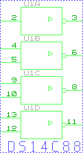
| DS14C89 |
4 * RS232->TTL |
Converts signals +3/-3 to 0/5V
compatible TTL levels |
single power 5V |
| DS14C88 |
4*
TTL->RS232 |
Converts signals
TTL en +3/-3V min |
double power
+ 6V# /- 5V |
This circuits like the max232 are inverters. As far as concerned
the chip DS14C88, it needs at least 6V to works correctly. The most
easiest way to solve this problem is to replace the chip by a single
transistor PNP shown below:
-
 |
This gives always an inconvenient : you should
use an symetric +5/-5V power supply..
If, in the circuit, nothing requires -5V then, the good thing is
to use an max232. |
B- RS232 Encoders/decoders
- The link mode can be synchronous (the last mode requires an extra
wire for a clock ) or asynchronous (the frames arrive randomly and are taken
into account immediatly ). As the RS232 is a seria lasyncronous link, the HP48 should ever
listen his serial input port in case of a frame is being adressed.
-
- There are two means of managing frames: the active lookup
(we wait a frame arriving and we do nothing else) and the passive lookup (in this
case, this could be either an external chip doing the job such as an UART -
Universal Asynchronous Receiver Transmitter or the processor triggered by an
Interruption to decode the frame).
-
- If we want to extract the 8 bits of from the serial frame our HP
nicely encode into a serial frame between the start and the stop bit , we can then use a
specialized chip from the UART family . Unfortunately, making these working is quite
difficult as these must be set up by software which is not accessible for common
people. The idea was to find an UART which can be set up by harware ie by putting logical
level on its pin to define the transfert rate, the number of data bits per frame.
-
- I have found hhis sort of chip, see my realization Lab48 to
learn how to use it, it is the AY3-1015D (cost 150F) - It is true that it is not get one
because it was the first generation of UART inside the PC keyboards. Don't worry , i have
found a cheaper replacement thz PIC16C84 (64F), programmable in C through the seria liinks
thanks to the fabulous pic programmer pip02 of JDM.- I will expose this
solution inside my project Hpdomotic.
-
- The principle of UART is to synchronize on the
positive edge of the start bit , read
- lthe state in the middle of the 8 data bits (this requires
an clock at least 2*Tbaud -
into la HP , there is a clock 16 time faster for it) and to memorize all the
separated bits into a 8bit widereception buffer. The content of the buffer can be
accessible directly on 8 pins of the chip or dynamically read by a
microcontroller.
-
2) The Infrared systems
- A - IR Interface:
- a) Half solution in wired logic
- I manage to get on the intenet , an wired
solution from Tony Duel.. I have not tested it and i don't know if it works but I
give you on the ASCII-ART form..

where the phototransistor is an Maplin YY66W (Infra
Red Sensor) = TIL78
and the infrared diode a Maplin YH70M (Infre-Red Emitter) = TIL38
In fact , in this circuit we notice an max232 who
transforms the modified IR frame to make it compatible to RS232.
This do not solve the problem we got to decode RS232 frame either.
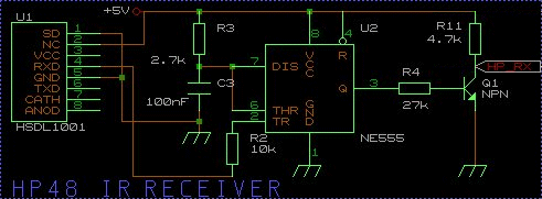
b) My IR interface
The problem can often be solved with a good choice of
electronic components.As Hewlett Packard is also recognized to be a great
manufactuer in the domain of the optoelectronic, why not choose its products? Two years
ago, I was interrested in Irda stuff.(transfert between PC <-> laptops by ir ).
There are some Irda modules as well at Temic (Siemens Telefunken) as Hp, ready to
run called the "Infrared IrdA Compliant Transceiver". I bought one of
each, and hopping it will works and my dreams has became reality.
The chip HSDL-1001 (available at Radiospares in France for
30 f ) who contains a photodiode and a infrared diode (with UV filter) and TTL
buffers, is adapted to transmissions up to 115kbit/s with an wavelength between 850 and
900 nanometers (the infrared diodes inside of the hp48 are optimized at 880nm ).

All the secret of this cicuit remains into the length of
the pulse . The well known chip NE555 is wired as an retriggerable monostable : for
every negative pulse presented on the TR pin(trigger), we get on the
output an hight pulse calibrated at :
Tw= R3*C3* ln3
In our case , it gives : Tw=297 microseconds who should be
less than the duration between two pulses ( 416.7 microseconds). Thus, we will have the
time to read correctly the level of the pulse (if there is) which is the complement of the
bit sent.(0= a hight pulse at 1 level of duration 267 microseconds, 1 = no
pulse then a 0 level of duration 416.7 microseconds).
Unfortunately, the chip HSDL-1001 can not be employed for the
emission too. Indeed, in the technical documentation, the maximum duration allowed
for the pulse at hight state is only 2.15 microseconds ( Irda compliance) and
we need in fact 52 microseconds. Let's use then an easy transistor amplifier
(Q2= BD139) for it.

B - IR: Encoder / decoder
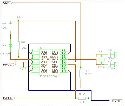
The choice is easy as the chip 16C84
from Microchip is reprogrammable and the tools are free. It is a 8
bit micocontroller with internal 1024k flash and the software can be
developped with C tools. It is easy to transform it into an serial UART and IR
decoder for the HP.

The Clock , prog and data signals are used by the
programmer. People should here know than Pip02 of JDM can not programs the chip on circuit
when the ground of the PC is used (Scopemeter on PC shortcuts the programmer by ground
loops!!!) however, the programmer is universal and easy to build. By the way,
big thanks to JDM.
I optimized an circuit in the french magazine "Electronic pratique". I
will give you the schematics as soon as the hpdomotics project will be finished.
|

