| Creation date: | 21.07.2001 |
| Chapter date: | |
| Author(s): | hpbaby |
| Navigator: |

| Version: EN | |
|
|
| Best in:1024*768 | |
|
|
|
||||||||||||||
THE SIMPLIFIED THEORY |
To exchange
data with outside, la hp48 uses: 1) An serial RS232 port type in full duplex at 9600 bauds max: Male connector with 4 pins spaced by 2 mm ( The female connector is difficult to get) hidden in front of hp .
The signals are the ground signal, TX send pin, Rx receive pin and the shield pin for EMC protection (Electromagnetic Compatibility)- By the way, you will notice on the official wire HP/PC (wire with Subd9/25 IBM PC: HP 82208A, MAC: 82209A), a cylinder greater in diameter than the wire, it is a parasite attenuator).
The transfer rate (who matches the bit fréquency) can be set up to 1200/2400/4800/9600 bauds, with 1 bit start, 8 bit de données , 1 or 0 parity bit (odd,even,none, mark or space) and at least one stop bit . The voltage V between (Tx/Rx) pin and the signal ground pin should vary inside +3/-3V range to +12/-12V range to respect RS232C normalization. You should observe that the logic is negative with Rs232 signals: a bit at "0" logical level correspond to an analogic voltage +V whereas a bit at "1" logic state is represented by an analogic -V voltage..
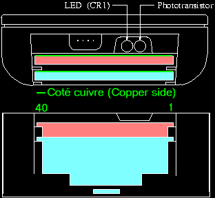
The input buffer can store a maximum of 255 bytes. It is possible to send and reveive at the same time to differents bytes on the serial port. 2) An Infrarouge Half duplex port at 9600 bauds max The reception and the emission can't be done at the same time. Depending on the bit to send, the infrarouge diode, protected by the ambient light lumière with the utlraviolet cache, provides a glitch or not. The features of the glitchs (high time, time between two succesive glitchs) should be very precise .( at the microsecond) to allow the correct reception of the IR frame on the other side.
The maximum transfert rate is given by the relation Speed_in_Bauds/11.375 indicating that ther is an exchange of 844 bytes/seconde at 9600 bauds). The distance at the emission is about d'en 2 à 3 meters although the reception, is limited to 20 centimeters.(This is due to some little genious guy who has exchanged answers by infrarouge with the A version of the HP48SX during examinations. Unfortunately for them, they have been catched and HP in france must have been forced to rectify future versions by Educationnal French Institute.) - Only the A version of HP48S(X) are not limited in receiving, for the others , it is required to open the hp and change a resistor (I have never done it as the screen is so fragile); 3) Two extended slot cards (only SX/GX): When a card is inside one of the two ports,the batteries of the hp replace the backup button of the card (type 2016). It is then possible by building a false card to know if the hp is on or off. The signals of the adress/data bus and some control signals are available. I give below the circuits to build a card by yourself .( I decline all responsabilty of the bad use of this and of any damage that may occur).
As express demand of Asterix86, I have make it clean Layo, alls the drafts one of my friend gave me.
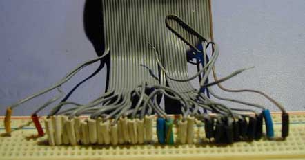
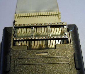
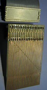
To avoid damages caused by the bad orientation of the card, I have build a chipless card with only connectors :
|
||||||||
| Basic
System The hp48 (S/SX/G/GX): |
|||||||||
| The I/O ports 1) The serial RS232 port 2) The Infrarouge port 3) The port for slot cards Reférence: |
|||||||||
| Adaptation
interfaces: 1) RS232 2) IR |
|||||||||
| Talking
fundamentals: 1) RPL |
|||||||||
| Stuff
required: the starter kit 1) The toolbox |
|||||||||