| THE HIGH RELIZATIONS |
The
microcontrollers which are autonomous and clever chips, are everywhere (in your car for
example).
However, it requires special development and programmation stuff to make it work and
make tests. It is often very expensive and student can't afford to buy even a kit. I
discover at microchip , a magic
microcontroller very cheap and simple to program. so maic that the chip in question
is used to hack palystations and sattelite...
What I was looking for, was a chip programmable in C (many times), cheap, with free
development tools and requiring no special hardware to program.
I had in mind to build a embedded cicuit : a universal domotic center controlled by
a PC and/or a HP or standalone. I was very happy to discover that
the microcontroller pic16F84 (8 bit CMOS EEPROM micontroller, 1 kword flash, 68byte RAM
,64byte EEPROM) , didn't need a "gas type" programmer and the development
tools , piclite C ompiler,
were free and unlimmited at htsoft (I recommend you to download piclite C compiler
there)
I - Hardware part
I started with the wonderfull pic programmer of JDM, pip02
- big thanks to you JDM.
The tools I use on PC to program the chip is the extra
icprog
from BONY GIJZEN (great! thanks a lot) with its nice window interface.
The JDM programmer is universal and unique as it allows you
to program 24cxx serial eeproms without external power supply.
Nevertheless, it has not allowed me to program in ciruit the chip
as announced.because there is a negative reference for the ground
signal and my scope on the PC made ground loops with it. I have
burned many pic 12c508 with it (one time programmable chip)
to build my own uir module. I will would
like to thanks here the original author, Ties
Bos.
Now, as I wanted to withdraw the chip from the circuit and to put
it on the programmer every time of program change , I have optimized
the jdm programmer by using ideas in the french electronic magazine
, Electronic pratique and adding some features (JTAG, autorestart
after code uploading, ...). Moreover, it can programs other microchip
controllers, just change chip connections.
Below , here is the component
side

|

The wire on the top is to be connected to a serial port of
the PC
The wire at middle height is the J-TAG to program the chip in circuit
The botom 9V type coupler allows to supply the programmer with a voltage
at least of 12V. . |
Conmément au prelative to the schematic below..
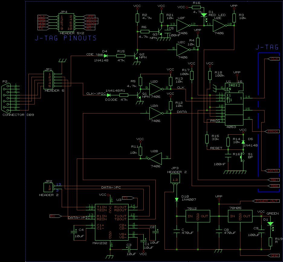
I have many comments to make:
The circuit is protected through D10 diode against bad polarisation of the
power supply. The max232 has two chanels available that can be used on the JP2
connector.The JTAG connector is a HE10 (2 rows*5 pin) .It carries 3 programmation
signals CLK, PROG et DATA and is designed to supply the target circuit. This
will be our case with the target card I called PICSYS (see next chapter). When the
circuit is powered through JP3, the green led ligths on (power check VERT). In
addition, when the chip has been programmated , it is possible to read the logic levels of
RB6 and RB5 through the programmer. During the programmation with ICPROG or pp2, the
red led (ROUGE) should blink.
Be aware that the programmation will fail if, on your
target circuit, you ommit to put pull-up on the interrupt pins you use
(this problem is for RB0, RB7, RB6, RB5 or RB4) else let the pin unconnected (not
recommended). Never these pins should be on low state (pull down or load) else the
pic16F84 microcontroller will stop the programmation on its own, as it
notices an interruption. In such case, the programmation fails and a error
message is delivered on ICPROG.(be sure you check si verify during programamtion
checkbox)
I give below the component mapping and the layout side,
Technical Note: All the layout design has be done first on
paper by me and put it clear on Layo1e. Here is the layout file picdev.lmc.
II -Software part
I have used the combination of two softwares : piclite C ompiler, and
icprog (to download) . The first is a
C cross compiler for the PICC16X84 meaning that
it compiles C programs on PC for only this type de microcontroler . The second
is the downloader tool to send the previous generated file ( binary .hex) into
the target circuit. You will see the result at the end of the programmation.
A) PICLITE:
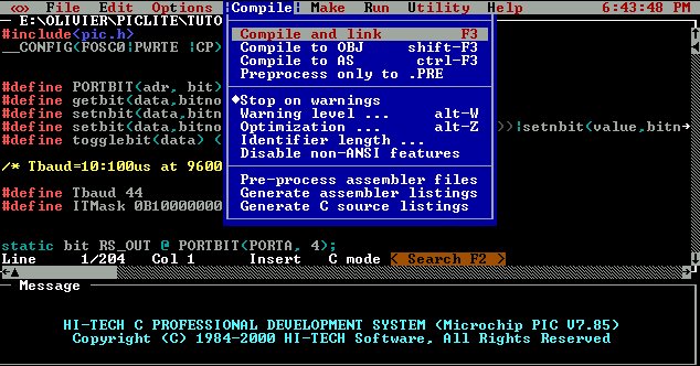
The interface is similar to Borland C++ on DOS . When you compile a file for the
first time (by pressing the key F3) on piclite,
questions are asked to you at the beginning :
-select midrange processor : select 16F84 (F=Flash release)
-select float type: 24 bit (for me it is enough)
-select computer optimization: Full
-select output format: The format to choose ( icprog compatible) is .hex intel.
-set map and symbol options: F4 - answer by OK , don't change anything.
The comipler will generated from your file.c (if correct of course) ,a file.hex
in the same directory . This is this file, we will upload on the
microntroller (on the targe circuit PICSYS) thanks to our PICDEV programmer.
B) ICPROG
Before you use it, you has to define by pressing on F3, the serial port you
connect the PICDEV programmer without forgetting to declare
the type of the programmer (jdm programmer) . Then, give the chip to program as described
below:

In Options form menu Settings , valid "verify
during programming" ans unvalid "ask when programming".
Load your file.hex (shortcut key: CTRL-O) and launch programmation with F5. If
you get an error like "verify failed at adress xxx",
it is due to:
1) your programmer is not conneted to the right port, (try to declare an another one)
2) your programmer (only for PICDEV) is not powered - The green light is on? power
ok?
3) you forget to connect the J-TAG to the target circuit
4) you have a pull-up problem on your target card as mentionned previously.(the red
led lights on and goes off jut after without blinking)
Tip:
There is an faster alternative for programing the PIC16F84
(upload in 6 seconds only!), the dos pp2.exe command from JDM .
I have set up piclite like this : under the utility menu , choose define user
command , and fill as shown :
| Menu Entry |
Command string |
| Upload |
pp2 16x84 P $(outfile) 1 |
My programmer is on serial COM1
port of the PC and the program pp2.exe is in the same directory as the .c file
to compile and to upload. Just press ALT-F7 to upload the program into the target -
much more easier for developments.
|


