Creation date 21.07.2001
Chapter of:
Author(s): hpbaby
Navigator: previous main
Version:     EN

Best in:1024*768

THE HIGH REALIZATIONS

The HP48IR protocol


Specific to the HP48 calculators this protocol is an adaptation of the RS232 protocol to exchange data by an Infrared link. The signal is built with pulses to save power of the batteries.


I - THEORIC SIDE

1) The complete frame

It is the result of 10 patterns spread into 3 blocks like this:

with ?=0 or 1 for the pattern value (depends on the block to transmit).


2) Meaning of the blocks


START:Marks the start transmission and allows the reveiver (hp48) to synchronize
DATA:Contains the 8 bit width char to send
STOP:Declares the end of the transmission to the receiver for this frame

3) Basic patterns

Here are the elementary and repetitive pieces of the electric signal :

  • representing either 0 or 1 , the value of the pattern.
  • forming the whole frame.


Pattern
START
D0 à D7
STOP
Possible values
0
0
1
1
Representation

Warning, the glue between each pattern is not shown here.

4) The dynamic model

Difficulties to understand? then look at this. The datas (or several control fields, ie not constant) of the frame are located in the patterns of the frame that can be changed. These are represented for you by buttons you can manipulate. The value on the buton is either the value of a block (see the meaning in paragraph 2 ) or the value of the pattern. Click on the buttons , observe , et analyze what happens on the electric signal..
  • if the frame is

  • then electricaly , the signal will be:


Try now do do the inverse : take one electric signal , deduce the value transmitted for each pattern you see, calculate each bloc value and guess what action is triggered. Click on one or more pattern on the signal and you will get the answer! If you let your mouse cursor on one pattern, you will even get its name.


HP48IR PRATIQUE

II - PRATICAL SIDE

1) Decoding an HP48 infrared frame

Just have a look on the basis patterns..you will notice that the value of the pattern is the inverse read on the pulse. Hereby , you need to invert the signal before reading taht is done with a un transistor . Unfortunately , we have seen previously thta our PIC16F84 microcontroller (see PICSYS) is not able to see such tiny pulses (52 microsecondes pulse duration on the white signal < tirqlatency=60microsecondes ), so you have to stetch out the pulses to 300 microsecondes (< duration of the pattern 416.7 microsecondes) with a NE555 chip wired in retriggerable monostable. You will have to read at the half extended pulse (generated by the infrared port of the HP48 placed at 1 to 2 meters ) to get the pattern value.

The yellow signal below comes from the pin labelled RX_IR.

Same operation à RS232 protocol, I jump over the START pattern and start reading from the half pulse pattern ie D0.


Then, I wait a pattern duration and I read the pattern and so on for the others data patterns.. In this sample, the 8 bit value read is 0 (null char).

Level read on the signal 0 0 0 0 0 0 0 0
Total
Binary value of the pattern (direct read) 0 0 0 0 0 0 0 0
Multiplicator (binary weight) 1 2 4 8 16 32 64 128
Résults 0 0 0 0 0 0 0 0
0


Other transmit..My scope seems not to have seen the last low pulse..

Try to deduce from the signal the value of char sent. I help you by giving the start Je vous aide and the end...

I you got trouble, just a clue : chr(valeur)='r' (ascii value)

Level read on the signal 0 ? ? ? ? ? ? 0
Total
Binary value of the pattern (direct read) 0 ? ? ? ? ? ? 0
Multiplicator (binary weight) 1 2 4 8 16 32 64 128
Résults 0 ? ? ? ? ? ? ?
?


You have found it? Congratulations!


2) Encoding an HP48IR frame

Here is the interface I use for emission to the HP:


In fact you should, generate by soft a high 52us pulse duration for 416.7us if the la value of the pattern is 0 else nothing ie low level during 416.7us.

On the left , I show the copy (in white) of the char received (in yellow),

I choose to emit the 0 value , that gives a a maximum of pulses.Is can be considered as a reference value.


The hardest job is to be very precises for the delays...


Other sample ..l sent the char 72 . Easy to determine here as all the pulses for this value are on the scope.

Level read on the signal 0 0 0 1 0 0 1 0 Total
Binary value of the pattern (direct read) 0 0 0 1 0 0 1 0
Multiplicator (binary weight) 1 2 4 8 16 32 64 128
Résults 0 0 0 8 0 0 64 0
72

And finaly the last sample for the road...

Which char I have sent?, please help me!

A clue : its root gives a integer ..

Level read on the signal ? ? ? ? ? ? ? ? Total
Binary value of the pattern (direct read) ? ? ? ? ? ? ? ?
Multiplicator (binary weight) 1 2 4 8 16 32 64 128
Résults ? ? ? ? ? ? ? ?
?


III - PROGRAM

Here I expose my program to estabalish the link between my HP and the PIC16F84 board (PICSYS).

hp48ir.c

#include <pic.h> //obligatory

//Quartz 4Mhz
#define PIC_CLK 4000000

//The delay routines
#include "delay.h"

//I use a chrystal and my code is not protected
__CONFIG(FOSC0|PWRTE |CP);

/**
* RS232 link management at 9600 bauds
*
*/

//This replaces bitfields implementation

#define PORTBIT(adr, bit) ((unsigned)(&adr)*8+(bit))
#define getbit(data,bitno) ((data>>bitno)&0x01)
#define setnbit(data,bitno) (data<<bitno)
#define setbit(data,bitno,value) (data&(~setnbit(1,bitno))|setnbit(value,bitno))
#define togglebit(data) (data^0x01)

//Duration in microsecond (the microcontroler is blind during this duration if the signal change on its 'IT interruption pin)
#define TirqLatency 60


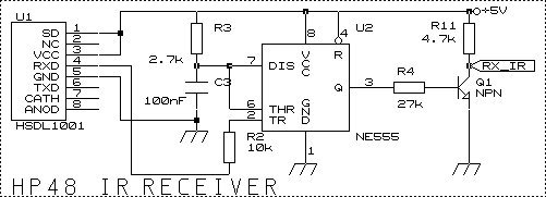
/******************** IR HP48 **********************************/

//Receiver parameters
//-----------------------

#define Tbit_rx_HP48IR 416 // 1/2400 bauds
#define Duration_HP48IR_rx_pulsehigh 300 // les 52us ont ‚t‚ rallong‚s par le NE555 … 300us
#define Jump_over_HP48IR_rx_startmotif (Tbit_rx_HP48IR-TirqLatency+(Duration_HP48IR_rx_pulsehigh/2))
#define Nb_HP48IR_rx_databits 8
#define Jump_over_HP48IR_rx_datamotif (Tbit_rx_HP48IR-40)

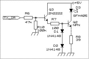
//Emitter parameters
//----------------------

#define Tbit_tx_HP48IR 416 // 1/2400 bauds
#define Duration_HP48IR_tx_highlevel 52
#define Duration_HP48IR_tx_lowlevel (Tbit_tx_HP48IR-Duration_HP48IR_tx_highlevel-50)
#define Nb_HP48IR_tx_databits 8
#define Nb_HP48IR_tx_stopbits 2
#define Duration_HP48IR_tx_stopmotifs (Nb_HP48IR_tx_stopbits*Tbit_tx_HP48IR)


#define ITMask 0B10110000

//---- Pin attributions -------------

static bit HP48IR_IN @ PORTBIT(PORTB,5);
static bit HP48IR_OUT @ PORTBIT(PORTB,6);

//To display voir the char on a 8 leds panel
volatile bit D1 @ PORTBIT(PORTB, 3);
volatile bit D2 @ PORTBIT(PORTB, 2);
volatile bit D3 @ PORTBIT(PORTB, 1);
volatile bit D4 @ PORTBIT(PORTB, 0);
volatile bit D5 @ PORTBIT(PORTA, 3);
volatile bit D6 @ PORTBIT(PORTA, 2);
volatile bit D7 @ PORTBIT(PORTA, 1);
volatile bit D8 @ PORTBIT(PORTA, 0);

//---- Working variables ---------------------------
//used by the delay routines
volatile unsigned int timeout;

//buffer variable
unsigned char Buff;

unsigned char TxBuff; // char to send
unsigned char RxBuff;// char received

//------ Declaration of the HP48IR routines -------------------------------

void HPget(void); /* Receive an IR frame from HP and decode it*/
void HPsend(void); /*Send a char to HP48 by the IR port(SFH405)*/

//-------Panel Leds routines -------------

void WriteParport(void);
void ReadParport(void);

//------ Main program to init ports and allow interrupts---------
main()
{

//Indicate pin direction (INPUT /OUTPUTS)
TRISB = ITMask;
TRISA = 0;

//Set the default pin levels
PORTA = 0;
PORTB = 0b10000000;
HP48IR_OUT=1;

//grant the interrupts on the port B
RBIE=1;
GIE=1;

//infinite loop to disturb
for(;;) {

}

}

//-----Show the Buff content on the 8 leds panel
void WriteParport(void) {

D1=getbit(Buff,0);
D2=getbit(Buff,1);
D3=getbit(Buff,2);
D4=getbit(Buff,3);
D5=getbit(Buff,4);
D6=getbit(Buff,5);
D7=getbit(Buff,6);
D8=getbit(Buff,7);

}

//----Retreive the value of the 8 leds (D1-D8) and store it into Buff .
void ReadParport(void) {

Buff=setbit(Buff,0,D1);
Buff=setbit(Buff,1,D2);
Buff=setbit(Buff,2,D3);
Buff=setbit(Buff,3,D4);
Buff=setbit(Buff,4,D5);
Buff=setbit(Buff,5,D6);
Buff=setbit(Buff,6,D7);
Buff=setbit(Buff,7,D8);

}

unsigned char prev_portb=0B10000000; //latch the value of B port

// Interruption routine triggered by a signal change (and lasts more thanTirqLatency!) on any pin:
// RB7, RB6,RB5,RB4 and RB0

interrupt isr()
{


//Try to know which pin change..
if (RBIF)
{
RBIF=0; //Interruption acquittment

if ((prev_portb ^ (PORTB&ITMask)) == 0B00100000){


//C'est la Broche RB5=HP IN which has changed, a char need to be analyzed.

if ((PORTB & 0B00100000) == 0) //If it is the falling edge of the start bit then
{

//receive the char behind
HPget();
Buff=RxBuff;
//display its value on the panel leds
WriteParport();
TxBuff=RxBuff;
//and send it for acknowledgment
HPsend(); //la liaison HP est half duplex - attention à la casse!
//RSsend();


}


}


prev_portb=PORTB&ITMask; //Next char..

}


}


// HP48 IR routines
//-------------------

//Receive a HP48 char by the use of the HSDL1001 infrared interface.

void HPget(void){

unsigned t;

//Jump over the start pattern and select the half pattern
//(D1 has been used for debug.)

//D1=1;
DelayBigUs(Jump_over_HP48IR_rx_startmotif);
//D1=0;

//Read the 8 data patterns

for(t=Nb_HP48IR_rx_databits;t--;) {

//get the value pattern and stores it at the good position in RxBuff
RxBuff=RxBuff | ((HP48IR_IN&0x01)<<(Nb_HP48IR_rx_databits-1));

if(t > 0)
RxBuff=RxBuff >> 1;

DelayBigUs(Jump_over_HP48IR_rx_datamotif);
//D1=0;

}


//Stop patterns ignored..


}

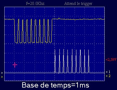
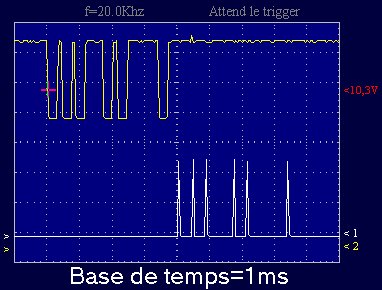
/* Send a char to HP48 by IR
* Pattern 0=Pulse 52us ,Pattern 1=no pulse, Tir=416.7us
**/

void HPsend(void){

unsigned b;
unsigned IR_Data;


//Start pattern
HP48IR_OUT=1;
//D1=1; for debug
DelayUs(Duration_HP48IR_tx_highlevel); //warning : we use DelayUS because 52 <255

HP48IR_OUT=0;
//D1=0;
DelayBigUs(Duration_HP48IR_tx_lowlevel); //416.7-52=364us Low Pulse


//Generates data patttern signal each Tir=416.7us
for(b=Nb_HP48IR_tx_databits;b--;) {

IR_Data=TxBuff&0x01;

if(IR_Data==0)
HP48IR_OUT=1;
//D1=1;

DelayUs(Duration_HP48IR_tx_highlevel);

if(IR_Data==0)
HP48IR_OUT=0;
//D1=0;

if(b>0)
TxBuff=TxBuff>>1;

DelayBigUs(Duration_HP48IR_tx_lowlevel); //416.7-52=364us Pulse bas ; 364 >255 so use DelayBigUs

}


//stop pattern
HP48IR_OUT=0; //optional
DelayBigUs(Duration_HP48IR_tx_stopmotifs); //2*416.7

}


Lab48 :
Scope for HP and
signal generator +5/-5V 
with 8 logical Inputs/Outputs
Hpmodem :
To dial by an radio link between
2 HP - externals power supply are required
Hptalk :
How to spell alphabet letters with HP by the use a vocal digitalizer from ISD
HpDomotic  :
1)Build your PIC  programmer (picdev)
2)Build you domotic interface  (picsys)
3)The multiusage Infrared module
  a)IR management of the HP
  b)Serial management HP / PC
  c)Encoding/decoding  RC5 frames
  to :
   Control PC , TV, Recorder.